REVIT FOR INTERIOR DESIGNERS
  • Home
  • LET'S BUILD THIS!
  • How it Works
  • Register
  • The Revit Resource

The Revit Resource

Revit for Interior Designers

How to Create Dashed Ceiling Patterns in Revit for Demolished Elements: A Complete Guide

7/8/2025

 
When working with phased construction projects in Revit, interior designers and architects often encounter a frustrating issue: demolished ceiling elements don't display correctly on reflected ceiling plans. While the ceiling perimeter appears dashed as expected, the interior hatch patterns remain solid, creating misleading documentation.

This tutorial is part of our comprehensive Revit for Interior Designers:  Commercial Office Interiors Course - get access to complete project files and advanced techniques.
​
The Problem: Inconsistent Demolished Ceiling Display in Revit

Understanding the Phasing Issue
When working with a 2x2 acoustical tile ceiling that's been assigned to the "existing" phase and marked for demolition in the "new construction" phase, you'll notice a common problem:
  • The ceiling perimeter correctly displays as dashed lines
  • The interior hatch patterns (representing the tiles) remain solid
  • This creates confusion in construction documentation
  • The reflected ceiling plan becomes misleading for contractors

Why Revit Ceilings Don't Display Demolished Patterns Correctly
​

The issue occurs because Revit's phasing system only affects the element's boundary graphics, not the material's surface patterns. The acoustical tile material uses a solid hatch pattern that doesn't automatically convert to dashed when the element is demolished.
​
At Revit for Interior Designers, we've encountered this problem frequently in our training classes, and the solution requires creating custom materials and hatch patterns.

The Complete Solution: Creating Custom Dashed Ceiling Materials

Step 1: Create a Custom PAT File for Dashed Patterns
Since Revit doesn't include built-in dashed ceiling patterns, you'll need to create a custom hatch pattern using a PAT file. This is a crucial step that many Revit users overlook.

Creating the PAT File:
  1. Open Notepad (or any text editor)
  2. Type the following code exactly as shown:
 
;%TYPE=MODEL
*24x24DEMO,24x24 Demolished Grid 0,0,0,24,24
90,0,0,24,24
 
;%TYPE=MODEL
*48x48DEMO,48x48 Demolished Grid 0,0,0,48,48
90,0,0,48,48
 
Important Notes:
  • The semicolon (;) and percent sign (%) are crucial
  • The numbers (24, 48) represent the ceiling tile dimensions
  • You can create additional sizes by copying the pattern and changing the numbers
  • Each pattern needs a unique name (24x24DEMO, 48x48DEMO)

Step 2: Save and Load Your Custom PAT File
  1. Save the file with a .PAT extension (e.g., "ceiling-grid-demolished.pat")

Step 3: Duplicate Your Existing Ceiling Type
  1. Select your existing acoustical tile ceiling in the reflected ceiling plan
  2. Click "Edit Type" in the Properties panel
  3. Duplicate the ceiling type and rename it with a clear identifier  (Example: "2x2 Acoustical Tile - Demo")
  4. This creates a separate ceiling type specifically for demolished elements

Step 4: Create a New Dashed Material
  1. Use Edit Type under the new ceiling's properties
  2. Navigate to the "Structure" section
  3. Click on the material (typically "Acoustical Ceiling Tile 24x24")
  4. Open the Materials dialog by clicking the small button
  5. Right-click and duplicate the existing acoustical ceiling material
  6. Rename the new material with a clear identifier  (Example: "Acoustical Ceiling Tile 24x24 - Demo")

 Step 5: Save and Load Your Custom PAT File
  1. Go to your custom material's Graphics tab and Surface Pattern settings
  2. Click on existing Pattern
  3. Click "New Fill Pattern" and select "Custom"
  4. Browse to your saved PAT file and select it
  5. Choose the appropriate pattern size (24x24 or 48x48)
  6. Click OK to load the pattern into your material

Step 6: Apply the Dashed Material to Your Ceiling
  1. With your custom material selected, you'll see the dashed pattern in the preview
  2. Click OK to apply the material to your ceiling type
  3. Apply the new ceiling type to your demolished ceiling elements
  4. The ceiling will now display with proper dashed interior patterns
 
Understanding Revit Phasing for Interior Designers
​

Phase Settings That Affect Ceiling Display
  • Select ceiling to be demolished and adjust Properties
    • Phase Created = Existing
    • Demolished = New Construction
  • Under the current View Properties
    • Phase Filter:  Set to "Show All"
    • Phase:  Set to "New Construction" to view the demolished elements 
 
Best Practices for Phased Ceiling Plans
  1. Create separate ceiling types for each phase to maintain clarity
  2. Use consistent naming conventions for demolished elements
  3. Maintain a library of custom PAT files for different ceiling sizes
 
Advanced Tips for Revit Ceiling Customization

Creating Multiple Ceiling Sizes


To accommodate different ceiling grid sizes in your project:
  1. Modify the PAT file to include additional patterns
  2. Copy the existing code block and change the dimensions
  3. Ensure each pattern has a unique name
  4. Load all patterns into your project as needed  

Managing Custom Materials Across Projects     
  • Save custom materials to your project template
  • Export materials to share with team members
  • Use Transfer Project Standards to move materials between projects
​
Common Troubleshooting Issues

Pattern Not Displaying Correctly 
  • Verify the PAT file syntax is exact
  • Check that the material is properly assigned to the ceiling type
  • Ensure the phase settings are configured correctly
  • Confirm the view's phase filter is set to "Show All"

Pattern Scale Issues
  • Adjust the pattern scale in the material definition
  • Modify the numbers in the PAT file for different tile sizes
  • Test the pattern at different zoom levels

Why This Solution Works

This method addresses the core issue by creating materials that inherently display as dashed, rather than relying on Revit's phasing system to modify solid patterns. The custom PAT file generates true dashed hatch patterns that accurately represent demolished ceiling elements.

Conclusion

Creating proper dashed ceiling patterns for demolished elements in Revit requires a combination of custom materials, ceiling types, and hatch patterns. While this process may seem complex initially, it ensures your construction documents accurately communicate design intent.

I would like to acknowledge Doug Bowers and his article on this topic.
 
Want to master more advanced Revit techniques for interior design? These methods are part of comprehensive training programs that cover everything from basic modeling to complex design scenarios.

How to Create Glass Walls in Revit: Curtain Wall Tutorial in Revit for Interior Designers

7/8/2025

 
Creating stunning glass walls in Revit using the curtain wall system can elevate your interior design projects, but many designers struggle with its complex workflow. This step-by-step tutorial covers three methods for creating professional glass wall installations in Revit, from simple office entrances to challenging corner configurations.

Whether you're designing modern office spaces, commercial interiors, or residential projects, mastering Revit's curtain wall system is essential for creating realistic glass partitions and walls.

What You'll Learn About Revit Glass WallsIn this comprehensive Revit tutorial, you'll discover:
  •       to set up curtain wall systems for glass partitions
  •       real-world applications for office and commercial spaces
  •       instructions for creating corner glass walls
  •       techniques for door installation in curtain walls
  •       methods for seamless glass wall connections
  •       mistakes to avoid when working with Revit curtain walls
This tutorial is part of our comprehensive Revit for Interior Designers course - get access to complete project files and advanced techniques.

Understanding Revit's Curtain Wall System for Glass Walls
Before diving into specific applications, it's important to understand that curtain walls in Revit operate differently from standard walls. Unlike regular walls where you simply drag a door onto the surface, curtain walls require a more structured approach involving panels, mullions, and grid lines.

The curtain wall system allows you to create walls of multiple materials - in our case, primarily glass - with precise control over mullion placement and panel configurations. However, this flexibility comes with specific rules and limitations that we'll address throughout this guide.

Method 1: Creating Glass Office Entrances with Curtain Walls

Setting Up the Basic Curtain Wall StructureOur first example demonstrates creating a glass wall entrance for an office space. This involves replacing a section of a standard 4⅞-inch gypsum board wall with a curtain wall system.

Essential Revit Curtain Wall Configuration Settings:
Use Properties / Edit Type under Curtain Wall 1 in Type Selector to customize its settings including:
  • Enable "Automatically Embed" to cut holes in existing walls automatically
  • Use "Glaze Curtain Wall Panel" for glass surfaces
  • Set border and vertical grid lines to "Continuous" for vertical mullion emphasis
 
Step-by-Step Revit Glass Wall Implementation
  1. Wall Placement: Navigate to Architecture > Wall and select the curtain wall system. Snap to the center of the existing wall and drag to create your glass wall section.
  2. Reference Plane Setup: Use reference planes to mark where mullions will be placed. Focus on intermediate mullions rather than end conditions, as these determine your panel divisions.
  3. Height Adjustment: Modify the curtain wall height to match adjacent walls (typically 8'2" for our office example).
  4. Adding Mullions: Use the Mullion command with "All Grid Lines" to place mullions throughout the system.  I am using a custom 2x4 mullions in this design.
  5. Grid Line Creation: Add vertical grid lines where you need panel divisions, particularly where doors will be installed.

Installing Doors in Revit Curtain Walls
The door installation process differs significantly from standard wall doors:
  1. Family Loading: Load curtain wall door families using Insert / Load Autodesk Family and choose the Doors folder
  2. Panel Selection: Use the Tab key to highlight the specific panel where the door will be installed, then click to select
  3. Unpin the Panel: Remove the pin constraint that enforces the glass panel rule
  4. Panel Replacement: Select the appropriate curtain wall door from the walls menu to replace the glass panel
Pro Tip: The door will fill the entire panel width, so plan your grid lines accordingly for proper door sizing.

Want to learn more advanced door techniques? Check out our complete Revit for Interior Designers course for detailed family creation and customization methods.

Case Study 2: Corner Glass Wall Configuration

The Challenge of Corner Conditions

Corner glass walls present unique challenges in Revit, requiring careful planning to achieve clean intersections without visible mullions at the corner joint.

Implementation Strategy
  1. Dual Wall Creation: Create two separate curtain walls that meet at the corner, ensuring glass orientation favors the exterior on both walls.
  2. Height Standardization: Set both walls to the same height (8'2") to maintain consistency in our design.
  3. Corner Trimming: Use the Trim command to cut the corner intersection properly. This may create small wall slivers that need additional attention.
  4. Profile Editing: When corner conditions create unwanted wall extensions to the floor, use "Edit Profile" to manually define the wall's shape in elevation view.

Advanced Corner Techniques
For seamless corner glass connections:
  1. Mullion Removal: Delete corner mullions from both curtain walls
  2. Panel Modification: Select and Unpin corner panels and use "Edit in Place" to extend panels to meet at the corner
  3. Constraint Removal: Accept the breaking of parametric rules to achieve the desired visual result
Important Note: Using "Edit in Place" makes the curtain wall system non-parametric, meaning you cannot easily modify mullion spacing or panel configurations afterward.

Case Study 3: Half-Height Glass Wall with Cutouts

Complex Configuration Requirements
The most challenging scenario involves creating a half-height glass wall (3'6") with corner conditions in a wall cutout. This requires combining multiple techniques and careful attention to base offsets.

Implementation Process
  1. Base Offset Configuration: Set both curtain walls to a 3'6" base offset to create the half-height condition.
  2. Wall Profile Editing: Use "Edit Profile" to create accurate wall shapes that account for the sill condition and eliminate unwanted wall extensions.
  3. Grid Line Precision: Use reference planes to capture exact joint locations from CAD drawings or design specifications.
  4. Mullion Management: Add mullions to all grid lines, then selectively remove corner mullions to achieve the desired aesthetic.

Final Assembly Considerations
The final step involves the same "Edit in Place" technique used in the corner example, but with additional complexity due to the half-height condition and sill requirements. Plan this step carefully, as it will lock your design and prevent further parametric modifications.

Best Practices and Important Warnings

Design Sequence
  1. Plan First: Complete all grid line and mullion planning before making any permanent modifications
  2. Test Proportions: Ensure door and panel sizes work with your design before finalizing
  3. Save "Edit in Place" for Last: Only use this technique when you're completely satisfied with your layout

Technical Limitations
  • Non-Reversible Changes: "Edit in Place" modifications cannot be easily undone
  • Mullion Dependencies: Mullions require grid lines; you cannot add mullions without corresponding grid lines
  • Panel Constraints: Curtain wall doors must replace entire panels, not portions of panels

Best Practices and Important Warnings
  • Use consistent glass orientation (interior vs. exterior facing) throughout your project
  • Create custom mullion profiles for unique designs per project
  • Document your reference plane locations for future modifications
  • Consider creating multiple curtain wall types for different applications

Conclusion

Mastering Revit's curtain wall system for glass wall creation requires understanding its unique workflow and limitations. While the system offers powerful capabilities for creating sophisticated glass wall designs, it demands careful planning and accepts certain compromises in parametric flexibility.

The three case studies covered here represent the most common scenarios you'll encounter in interior design projects. By following these methodologies and respecting the system's constraints, you can create professional-quality glass wall installations that enhance your Revit models and presentation materials.

Remember that these techniques are part of a broader workflow that includes proper family management, material assignment, and rendering considerations. For more advanced techniques and complete project workflows, consider exploring comprehensive Revit training resources that cover the full scope of interior design applications.
 
Want to master more advanced Revit techniques for interior design? These methods are part of comprehensive training programs that cover everything from basic modeling to complex design scenarios.
​

Revit Family Folders Missing?

4/12/2025

 
Where Did the Revit Family Folders Go? Here's What You Need to Know

If you've recently upgraded to Revit 2024, you might have noticed something puzzling: the familiar Revit Family folders you’ve relied on for years are nowhere to be found. Don’t worry — your favorite doors, windows, furniture, and more haven’t vanished into thin air.  Autodesk has just shifted how we access them.
​
Let’s break it down for our Revit for Interior Designers...

What Changed in Revit 2024?  In previous versions of Revit, Autodesk provided local Family Libraries — actual folders full of .RFA (Revit Family) files — installed with the software. These folders were typically stored on your local drive, giving users quick access to default content organized by category.
​
Starting with Revit 2024, Autodesk is no longer including these folders by default as part of the installation. This change is part of their larger effort to streamline installations, reduce software bloat, and encourage cloud-connected workflows.
​
But don’t worry — the content is still available. It’s just accessed differently now.

How to Access Families in Revit 2024Instead of browsing local folders, Autodesk now encourages users to use the INSERT tab.

​Here’s how you do it:
  1. Open your Revit project.
  2. Go to the Insert tab in the ribbon.
  3. Click on Load Autodesk Family.
This opens a cloud-based browser where you can access the full suite of Autodesk’s default families — just like before, but now it's hosted online. You can search, filter by category, and download only what you need when you need it.

Benefits of the New System
  • Faster Installations – Without the large library files, Revit installs more quickly and takes up less space.
  • Cloud-Connected Access – You’re always using the most updated content directly from Autodesk.
  • Smarter File Management – No need to manage local folders or worry about duplicate content.

Want Local Access Anyway?

​If you prefer having the families stored locally (maybe for offline access or custom setups), Autodesk still provides a separate content download. You can grab it from the Autodesk Accounts portal or the Autodesk Knowledge Network and set up the folder paths manually in your Revit options.

Final Thoughts.

​Yes, it’s a shift — and like all changes, it takes a little getting used to. But once you get familiar with the Load Autodesk Family tool under the INSERT tab, you’ll find it’s a faster, more modern way to access Revit content. And for firms managing large teams, this also opens the door to more standardized, cloud-based content workflows.
So while the folders are “missing,” the families are just a few clicks away — and more accessible than ever.

Aligning drawings on sheets in Revit

3/10/2025

 
My recent class of Revit for Interior Designers asked how to place floor plans and reflected ceiling plans in the same location on multiple sheets.  In Autodesk Revit, Guide Grids are used to help align views consistently on sheets. They are particularly useful for maintaining a uniform layout across multiple sheets, ensuring that plans, elevations, and sections align properly when printed or presented.

Key Features of Guide Grids:
  1. Sheet-Specific – Guide grids are applied to sheets and do not appear in the model itself.
  2. View Alignment – They assist in aligning views (such as floor plans, elevations, and sections) consistently across different sheets.
  3. Customizable – Users can create multiple guide grids with different spacing to suit various layout needs.
  4. Visibility – Guide grids are visible only on the sheets where they are applied and do not print.
  5. Adjustable – The grid spacing and positioning can be modified to suit different project requirements.
How to Use Guide Grids in Revit:
  1. Open a Sheet – Navigate to a sheet where you want to use a guide grid.
  2. Create a Guide Grid –
    • Go to the View tab.
    • Click Guide Grid in the Sheet Composition panel.
    • Assign a name to the guide grid.
  3. Adjust the Grid – Click on the guide grid to modify its spacing or move it as needed.
  4. Align Views – Drag views (floor plans, sections, etc.) onto the sheet and snap them to the guide grid for precise alignment.  It is best to use column grid line intersections as guide grids do not snap to corners of walls.
Best Practices:
  • Use consistent guide grids across sheets to maintain alignment.
  • Adjust grid spacing to match key reference points in your views.
  • Utilize guide grids early in the documentation phase to avoid misalignment issues later.

Revit Tips for Interior Designers: Importing AutoCAD Elevation Drawings

9/26/2023

 
A common question I receive for interior designers is how to recreate an elevation, originally drawn in AutoCAD, while using Revit.  This concept is one that I use in my Revit for Interior Designers training course.

There are many advantages to using BIM, including improved collaboration, better coordination, and reduced errors. However, BIM models can be complex and time-consuming to create.

One way to speed up the BIM process is to import AutoCAD elevation drawings into Revit. This can be a great way to quickly recreate the 2D elevation views as Revit models.

Here is a step-by-step guide on how to import AutoCAD elevation drawings into Revit:
  1. Launch your elevation view in Revit.
  2. Click the "Insert" tab and then click the "LINK CAD" button (I suggest avoiding IMPORT CAD option as it brings undesirable AutoCAD elements into Revit)
  3. A window will open that allows you to browse to the AutoCAD file that you want to import.
  4. If you like, use Colors = Black and White to avoid importing AutoCAD layer colors.
  5. I would suggest using Positioning = Manual – Center option to select a point on the screen after importing your file
  6. Select the AutoCAD file and then click "Open".
  7. Use the Zoom All command (ZA) to locate your Autocad elevation in your Revit elevation view.
  8. If your AutoCAD file does not appear, I would launch your 3D View, select TOP on the View Cube, locate your Autocad file (should appear as a line), and drag it on top of your Revit floor plan.  Then, return to your elevation view and the Autocad drawing should appear. 
Picture
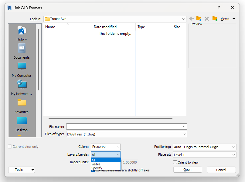
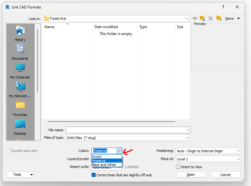
Here are some tips for importing AutoCAD elevation drawings into Revit:
  • If the AutoCAD drawing contains any layers that you do not want to import, you can turn those layers off before you import the drawing.  Use the Layers/Levels = Specify option
  • Once you have imported the AutoCAD drawing, you can use the Revit "Align" tool to align the drawing with the Revit model.
Picture
Importing AutoCAD elevation drawings into Revit can be a great way to speed up the BIM process and to create more accurate and complete Revit models.

Scope Boxes and Crop Regions: Tips and Tricks for Revit 2024 Users

8/31/2023

 
Revit 2024 is now available, but it is causing my past Revit for Interior Designers (& architecture) students to scratch their heads. 
  • What happened to the Imperial-Archtectural Template when starting a new project? 
  • What is new Imperial Multi-discipline template anyway?
  • What are these green, dashed boxes surrounding the view?
  • Why can't I deactive the Crop View option in Plan view?
Let's take this one step at a time. 

​For those that want to have Revit 2024 'look and feel' like prior releases, on the homescreen choose NEW, then the BROWSE button and choose either Commercial-Default.rte OR Residential-Default.rte depending on what type of project you would like to begin.
Picture

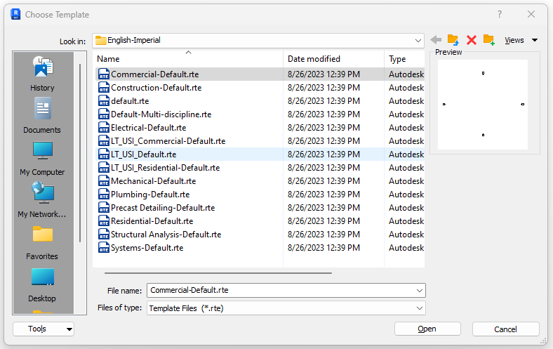
​You will notice that although the screen looks the same, the Project Browser has been updated with new floor plans that appear in each elevation view.   In addition, schedules and sheet have been added as well.
Picture

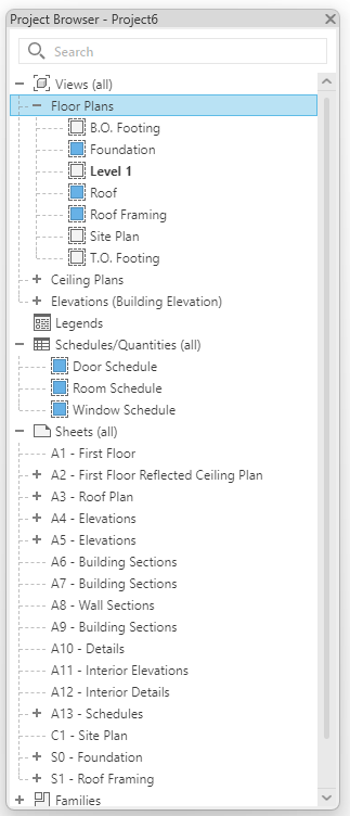
​However, I do believe there is value at least understanding what the Multi-discipline template has to offer and understand how to manipulate what appears on the screen.  In fact, it may be a good idea to add some of these techniques to your projects in prior releases of Revit.  

The first task is to understand the concept of Crop Regions and Scope Boxes.  Understanding these concepts will allow you to quickly use the new Multi-discipline template OR deploy these tactics in any Revit project.  Let's start by defining what a Crop Region does.  
​
The crop region command in Revit allows you to define the boundaries for a view. It is a rectangular area that can be drawn in any graphical project view. Once a crop region is created, it can be used to crop the view to its extents, or to control the visibility of elements in the view.
To create a crop region, follow these steps:
  1. Open any view.
  2. In the Properties panel, click Crop Region and Crop Region Visible.
  3. Crop Region activates the cropping
  4. Crop Region Visible determines whether or not you see the box that can crop the drawing
The crop region will be created and displayed in the view. You can resize or rotate the crop region by dragging the handles.

When Crop Region is activated, the elements within the boundaries of the Crop Region will be visible in the view, while the other elements will be hidden.
​
Here are some additional things to know about crop regions:
  • Crop regions can be created in any graphical project view, but they are only visible in that view and in 3D views.
  • Crop regions can be assigned to multiple views.
  • Crop regions can be resized and rotated (although I would avoid rotating the crop regions).
  • The visibility of elements in a view can be controlled based on a crop region.
  • Crop regions can be deleted.

Watch this video on the topic of using Crop Regions in Revit:

Next, lets discuss what a Scope Box can do for you in all versions of Revit
​
​A scope box is a Revit element that allows you to define the extents of a view. It is a rectangular area that can be drawn in any plan view. Once a scope box is created, it can be used to crop the view to its extents, or to control the visibility of elements in the view.
To create a scope box, follow these steps:
  1. Go to the View tab.
  2. In the Create panel, click Scope Box (make sure you are in a PLAN view)
  3. On the Options Bar, enter a name for the scope box and specify a height, if desired.
  4. Click in the upper left corner of the area you want to define as the scope box.
  5. Drag the cursor to the lower right corner of the area.
  6. Release the mouse button.
Scope boxes can be a useful tool for controlling the extents and visibility of views in Revit. They can be used to create consistent views of a project, or to focus on specific areas of a view.
Here are some additional things to know about scope boxes:
  • Scope boxes can be created in any plan view, but they are only visible in that view and in 3D views.
  • Scope boxes can be assigned to multiple views.
  • Scope boxes can be rotated and resized.
  • The visibility of elements in a view can be controlled based on a scope box.
  • Scope boxes cannot be uncropped.

Watch this video on the topic of using Scope Boxes in Revit:

Now that we understand the basics, how do we use both Crop Regions and Scope Boxes together to control the appearance of your Revit views.  This final video combines both concepts and allows you to customize the initial Multi-discipline template in Revit 2024 to start a project.

​Enjoy!!!

Revit Crashing on Startup? Here's How to Fix It! - Troubleshooting Tutorial

8/10/2023

 
Picture
Revit Crashing on Startup. How to Fix! Troubleshooting Tutoria
During the course of interior design, Revit stands as a great tool for innovation and creativity. However, what happens when your software decides to thwart your efforts by crashing on startup? In this blog post, we'll delve into a real-life journey of frustration, persistence, and ultimate triumph over a relentless Revit startup crash. If you've ever faced a similar challenge or are looking to preempt one, this story might offer you insights and solutions that conventional troubleshooting couldn't.

When Revit Said "No More"

The Trouble 
all began when I fired up Revit one morning, only to be met with an unfamiliar sight – the software crashed on startup without warning or error messages.  Like many, I turned to the web for solutions and Googled "Revit crash on startup." I meticulously followed the prescribed steps from Autodesk's support forums, hoping for a miracle.

You can follow the support site here: 

​https://www.autodesk.com/support/technical/article/caas/sfdcarticles/sfdcarticles/Revit-2017-crashing-during-start-up.html

Alas, the results were as disappointing as the crash itself. The solutions posted by Autodesk seemed promising on the surface, but they failed to yield any results. To make matters worse, my attempts to seek assistance from Autodesk's support desk proved useless, leaving me more perplexed than ever.
​
A Radical Move: Rebooting, Uninstalling, Reinstalling, and the Reformatting. 

​After rebooting my computer several times, 
and with my patience dwindling, I embarked on a radical path – uninstalling and reinstalling Revit. I tried to avoid this option as Revit is a very large program and you can quickly lose an hour of your time.  The fresh install offered a glimmer of hope as the software seemed to cooperate temporarily. I celebrated my victory, only to have it short-lived. The software would work for a couple of days and suddenly the crashing curse soon returned, rendering my hard-won solution null and void.  Finally, I decided that perhaps a virus infected by computer and decided to reformat my hard drive (and reinstall three years worth of software and customizations).  This process took days but same result; Revit crashes on startup!

The Turning Point: Enter Imaginit.com

Determined not to be defeated, I sought out professional help.  I contacted every long term Revit user I knew, but nobody ever experienced this issue.  Am I the first? Enter Imaginit.com, a software solutions provider and Autodesk reseller. With their expertise, we embarked on an intensive two-hour troubleshooting session. We delved into the intricate labyrinth of software conflicts, hardware inconsistencies, and more. They were professional, thorough and had extensive software expertise.  After an exhaustive examination, we reached a breakthrough.

The Unlikely Culprit: Trendmicro Antivirus
​
​
It turns out that the antagonist in this narrative was an unlikely one – my antivirus software, TrendMicro. The very software meant to protect my system was inadvertently wreaking havoc with my Revit experience. I have used this software exclusively for many years and NEVER had a conflict with Revit or any other software application.  Imaginit's experts determined that TrendMicro was conflicting with Revit, causing it to crash upon startup.

The Key to Victory: Adding Exceptions

​
The solution was both surprising and straightforward. We added Autodesk directories to the exceptions list within Trendmicro. This simple yet effective action paved the way to stability. Revit no longer crashed on startup, and I was finally able to access my projects without the looming dread of a crash derailing my efforts.
Picture
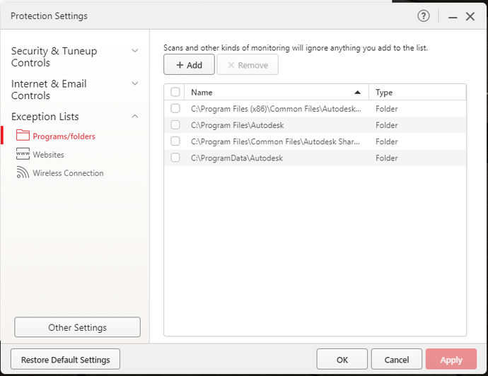
Conclusion: A Lesson in Tenacity and Adaptability
​

This journey through Revit crashing on startup taught me valuable lessons beyond troubleshooting steps. It reinforced the importance of tenacity, adaptability, and the willingness to seek outside expertise. While Autodesk's support channels faltered, Imaginit.com stepped in as the unsung hero, unriddling the mystery that plagued my creative process.
​

To anyone facing a similar ordeal, I offer this narrative as a testament that solutions exist even when conventional paths fail. If Revit crashes on startup have derailed your work, consider exploring avenues that extend beyond the ordinary. Sometimes, a fresh perspective and the expertise of professionals can make all the difference.
​

Let's make our architectural journeys smoother, our creative processes uninterrupted, and our Revit experiences crash-free (and LESS EXPENSIVE THAN MINE). After all, the most remarkable designs should be hindered by the least remarkable crashes.
​

Have you encountered a similar Revit crash saga? Or have you found unconventional solutions to software troubles? Share your experiences in the comments below! Let's continue the dialogue and help fellow designers overcome their challenges.

Produce Revit Renderings for Interior Designers using Autodesk Cloud

6/19/2023

 
Once of the most common questions I receive is how to create and improve renderings using Revit and its Autodesk cloud rendering service, A360.  The website can be found here (https://www.autodesk.com/products/rendering/overview) , however access to the cloud server is typically handled directly inside of Revit. 

What is A360 cloud rendering? It's a service that allows interior designers to produce high quality, photorealistic renderings on the cloud rather than their own computers.  Typically, rendering software is handled on your own computer making the process painfully slow based on your hardware.  A360 solves this problem by allow users to upload their projects to Autodesk servers and produce the renderings online.  

Interior design students enrolled at colleges and universities can download Revit for free and gain access to the cloud rendering service within the software itself.  In addition, interior designers and architects using Revit can purchase tokens to produce renderings online as well.

I hope this video will help answer your questions.

Get a Grip on a Wall Mounted Handrails in Revit

7/29/2020

 
    Modifying railings is not always the easiest task to accomplish in Autodesk's Revit.  In fact, some may think that process is more complex than customizing a curtain wall system.  When combined with editing stairs, I would have to agree that a majority of my students (and professionals) have the most difficult time with this process.  I will provide a series of blog posts that I hope will better explain how this process works in Revit.  I will begin by explaining how to convert your typical railing into a wall-mounted solution.

The following steps describe an exit stair with two railings, one against a wall (inside) and the other freestanding.

Inside railing is assigned to Railing Guardrail – Pipe style

Outside railing is assigned to Railing Handrail – Pipe style

Style of stair= Monolithic Stair

Additional steps are required to end the handrail at wall (outside railing) with pipe extension

Select outside railing and do the following:

Choose EDIT TYPE

Choose DUPLICATE and rename copy:  Railing Handrail – Pipe Wall Extension

Choose EDIT button under Baluster Placement:

Make all fields under Baluster Family=NONE (see image below). 

Uncheck Use Baluster Per Tread On Stairs

Press OK when done.
Picture
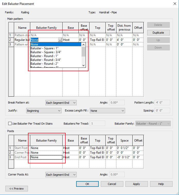
​Choose EDIT button under Rail Structure and use Delete to remove all fields
​
Press OK when done.
Picture
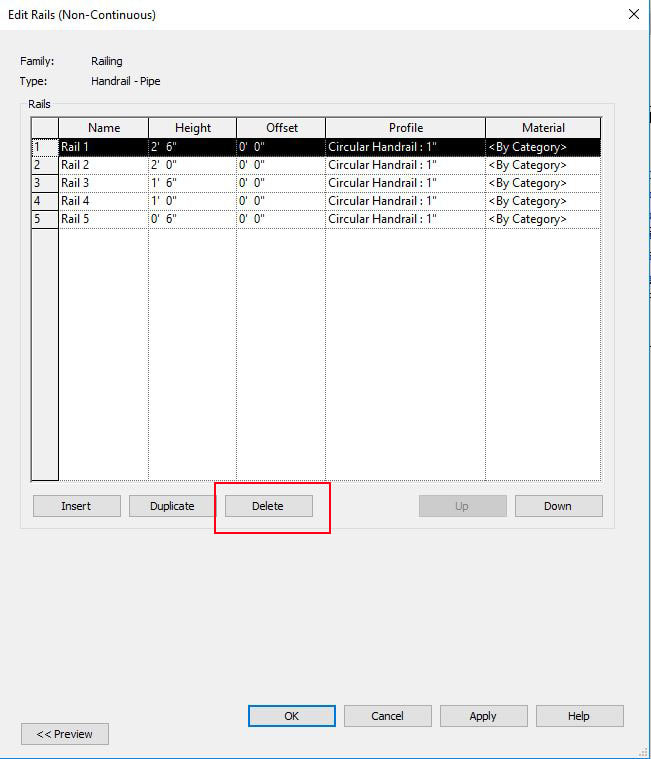
Uncheck Top Rail / Use Top Rail (see image below)

Choose button under Handrail 1 / Type option
Picture
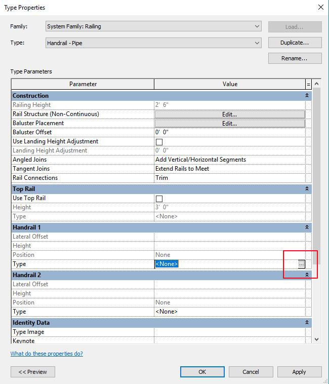
Choose Pipe – Wall Mount from Type menu

Press OK when finished
Picture
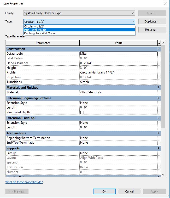
Review your 3D model and you will notice the changes made to your inside railing. 

Next, you will need to create a new handrail type where the handrail extends at the bottom and top of the stairs.  To do this, we will use the Families Menu.  In your Project Browser (see below), find Families / Railings / Handrail Rail Type / Pipe Wall Mount and right-click, duplicate and name it “Pipe – Wall Mount Extend”. This style will return the handrail to wall at bottom/top of the stair and extend 1'-0" beyond its current locations (see final completed stair design)
Picture
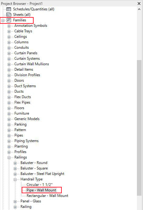
Right-click on the new Pipe – Wall Mount Extend type and choose Type Properties (see below)

​Copy the Extension Style and Lengths under both Extension menu as shown in the image below.

Press OK when done:
Picture
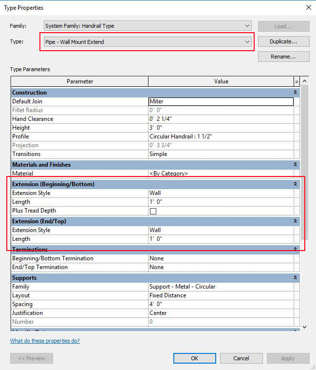
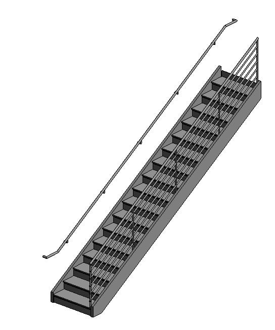
You have now created a new type of handrail that extends 1'-0" beyond the bottom and top of the stair run but you will need to assign this design to your customized railing.

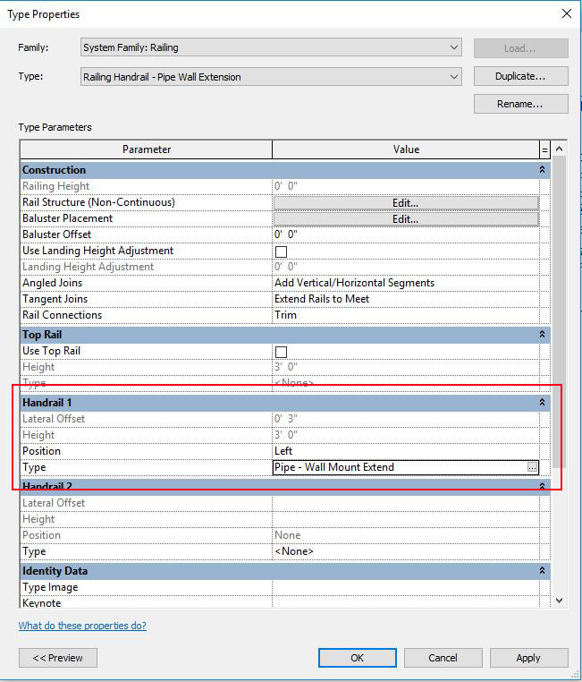
In 3D view, select the outside handrail again (Railing Handrail – Pipe Wall Extension), choose EDIT TYPE.
​
Under the Type menu, choose the newly created handrail type:  Railing Handrail – Pipe Wall Extend
Picture
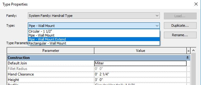
Under the Handrail 1 settings, change Position = Left and Type = Pipe-Wall Mount Extend (see image )
Picture
Congratulations, the stair design will now match the design (see image below)
Picture
If you have any issues following these instructions, be sure to watch my YouTube video that also explains the process.

Revit Panoramas Will Leave Your Head Spinning...

7/27/2020

 
Several websites exist that allow Revit users to upload their panoramas to the web.  These include websites like Eyespy360.com, Kuula.co, Roundme.com, etc. to name a few. These websites present immersive, panoramic tours of your projects while allowing clients to experience your designs in 360 degree presentations.  When combined with inexpensive products like Google Cardboard, suddenly virtual reality is in the palm of anyone's hand without resorted to expensive hardware like Facebooks' Oculus Rift and/or HTC VIve Cosmos VR headset.  Google offers a similar online toolkit using its Tour Creator website.   First, create your panoramas in programs using Autodesk's cloud rendering service directly from within Revit, use rendering programs like 3ds Max, V-Ray or live-rendering Revit plugins like Enscape3D, Twimmotion or Lumion.  In a few minutes, you can upload your panoramas to the web.  These can be then be shared with clients via email, hosted on websites, shared in your Blog posts, etc.  As you can see, there are plethora of methods available to provide your clients with the presentations they need to review your projects, share with community members, civic and business leaders and fundraising efforts.  Get started now and have everyone's head spin when they see your projects!
<<Previous
    Picture

    Author

    John Manfredy has over two decades of expertise teaching architectural technology to architects and interior designers.  Coursework has included Autodesk products:  Revit Architecture, 3D Studio Max, Autocad and SketchUp.  

    Read his recommendations on Linkedin to learn more about his desire to help design professionals succeed in their careers.  He is seen as a mentor who pushes you to your potential. He'll engage you in his class with his infectious passion for design technology as well as collaborative approach.

    Find John in the Facebook Group Page:  Revit for Interior Designers
    or YouTube channel:
    ​http://bit.ly/youTubeRevit  

    Archives

    July 2025
    April 2025
    March 2025
    September 2023
    August 2023
    June 2023
    July 2020
    May 2020
    November 2018
    October 2018
    January 2018
    December 2017

    Categories

    All

    RSS Feed

Proudly powered by Weebly
  • Home
  • LET'S BUILD THIS!
  • How it Works
  • Register
  • The Revit Resource